Drawing
Drawing is the process of converting the internal representation of a shape into an image on an output device. As noted in Figure 1-2 on page 1-12, a QuickDraw GX shape consists of several other objects in addition to a shape object. When you draw a shape, QuickDraw GX uses information from those objects and others to control how the shape is rendered. It uses the information in this order:
Drawing starts with geometry, a property of every shape object. The geometry defines the intrinsic dimensions of the shape. Those dimensions can then be modified, in several stages, until the rendered image appears on the screen or printer. The rest of this section describes in more detail how a shape's geometry is transformed as it passes through the drawing steps.
- the geometry of the shape object
- stylistic and color information from the style object and ink object
- clipping and mapping information from the transform object
- mapping and clipping information from one or more view port objects
- mapping and clipping information from one or more view device objects
Mapping and Clipping
Mapping and clipping are two of the principal modifications a shape undergoes as it is prepared for drawing, and each occurs at several steps along the way.A mapping is a 3 3 matrix that performs a mathematical transformation on a set of two-dimensional points, such as the geometry of a shape. Given any shape, you can use a mapping to control
Figure 1-4 shows examples of the effects of mapping.
- translating, or moving, the shape from one (x, y) location to another
- scaling the shape in the x-direction, y-direction, or both directions
- rotating the shape around any point
- skewing the shape
- changing the perspective of the shape
The transform object, the view port object, and the view device object each has a mapping as a property. Each object's mapping can affect the location, orientation,
scale, and other distortion of the shape as it evolves from geometry to rendered image (described under "The Drawing Sequence: Coordinate Conversion" beginning on page 1-28). Mappings are described more fully in the chapter "Transform Objects" in
this book, and in the mathematics chapter of Inside Macintosh: QuickDraw GX Environment and Utilities.Clipping is the restriction of the visible part of a shape to a specific area. The clip is the specific description of that visible area. Clips are often rectangles or similar simple shapes, although QuickDraw GX permits clipping to any definable shape geometry (rectangle, polygon, path, and so on), which allows for very sophisticated clipping effects. Clips can even be glyph shapes and one-bit-per-pixel bitmaps. For the rules and restrictions on clips, see the chapter "Transform Objects" in this book.
The transform object, the view port object, and the view device object each has a clip as a property. Each object's clip is applied at a specific point during the preparation of the shape for drawing (described under "The Drawing Sequence: Coordinate Conversion" beginning on page 1-28). Each further restricts the part of the shape that will ultimately be visible.
View-Related Objects
The transform object associated with each QuickDraw GX shape contains a reference to one or more view port objects. When you draw the shape, QuickDraw GX uses that view port reference to determine at what position on which physical device or devices to draw the shape. To do that requires that the view port and two other view-related objects, the view group and view device, interact as follows:
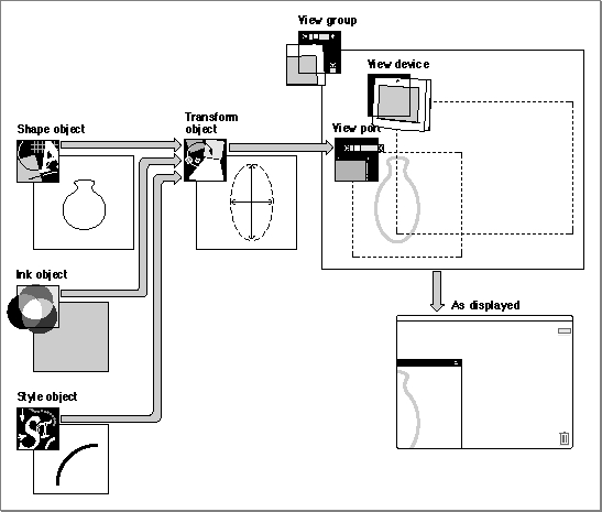
Figure 1-5 shows schematically how these objects interact as a shape is drawn. A shape geometry that defines a vase, a gray color defined in the ink object, a thick pen width defined in the style object, and a scaling in the transform object's mapping combine to make an elongated image of the vase. A portion of the vase appears on screen, where the clips of the view port and view device overlap.
- A view port object represents a drawing environment. A view port is analogous to a porthole on a ship. The view port has a mapping that defines the scale, orientation, and location of the porthole, and a clip that prevents anything beyond the edges of the porthole from being drawn. If you think of a view port as analogous to a Macintosh graphics port, the view port mapping defines the location (in QuickDraw global coordinates) of the port on the screen, and the clip defines the visible region of the port. Unlike graphics ports, however, view ports are device independent, and their mappings control much more than location: they can also define the scaling, rotation, skewing, and other distortion of shapes drawn in the view port.
- A view device object typically represents an actual, physical output device such as a monitor or printer. It, too, has a mapping and a clip that define its location and its visible (drawable) area. You can think of a view device as analogous to the Macintosh screen, in which case the mapping defines the location of the screen origin (and the size of the pixels too), and the clip defines the screen bounding rectangle. When a shape is drawn, it appears on a view device if the shape's view port intersects the view device. The object that controls the relative positions of view ports and view devices is the view group.
- A view group object represents a coordinate plane that provides dimensions and relative positions for view ports and view devices. A view group's coordinates have a specific dimension (unit distance is 1 point, or 1/72 inch). For all view devices that represent actual physical devices, QuickDraw GX defines their locations in the onscreen view group's coordinate plane. Your application then defines the locations of view ports on that plane, and thus controls whether or not the view ports are visible on the view devices. A view group is equivalent to the QuickDraw coordinate plane (or to an offscreen graphics world) on the Macintosh, and view group coordinates are analogous to QuickDraw global coordinates. However, unlike with QuickDraw, QuickDraw GX global coordinates have a specific dimension and are device independent.
Figure 1-5 How QuickDraw GX draws a shape
Figure 1-5 is a simple case in which a single shape and its transform are drawn to a single view port that partially intersects a single view device in the same view group. Quickdraw GX provides much greater flexibility, allowing for complex combinations of shapes, transforms, view ports, view devices, and even view groups:
For further discussion and illustration of these display possibilities, see the chapter "View-Related Objects" in this book.
- Several shape objects can reference the same transform object, allowing these shapes to be scaled, rotated, and otherwise changed in unison.
- Several transform objects can reference the same view port object, allowing shapes that are transformed in different ways to appear in the same view port.
- A single transform object can reference several view port objects, allowing a single shape to appear simultaneously (even with different scaling or orientation) in several view ports.
- View ports can exist in a hierarchy, in which one view port "contains" another, and thus its movement, scaling, and clipping affect view ports lower in the hierarchy.
- Within a view group, view ports and view devices can overlap in any combination. Drawing occurs automatically wherever the visible portions of any view port and any view device overlap.
- More than one view group can exist simultaneously, allowing for offscreen drawing. Furthermore, the view ports referenced by the transform of a single shape need not all be in the same view groups, allowing for simultaneous onscreen and offscreen drawing of a shape.
The Drawing Sequence: Coordinate Conversion
This section discusses the sequence of events, in terms of the mappings applied to a shape, that occur in drawing. To understand the details of the transformations that take place, you must understand the coordinate spaces whose relationships are determined by the mappings contained in various objects.The information given in this section is an abbreviated version of the discussion of mapping and clipping in the chapter "View-Related Objects" in this book. Please see that chapter for additional information, especially about the role of clipping in drawing.
QuickDraw GX Coordinates
A coordinate space in QuickDraw GX consists of a plane in which positions are determined by coordinates. All coordinates in QuickDraw GX are specified with fixed-point numbers in the range of -32,768.0 to approximately 32,768.0. Fixed-point numbers and the functions for manipulating them are described in the mathematics chapter of Inside Macintosh: QuickDraw GX Environment and Utilities. Coordinates are always written in the order (x, y), and for any coordinate space the point (0.0, 0.0) represents the origin of the space. Points that lie to the right of the origin increase in a positive direction along the x-axis; points that lie below the origin increase in a positive direction along the y-axis.QuickDraw GX allows you to work in four coordinate spaces: geometry space, local space, global space, and device space. You can work separately in each space as appropriate; QuickDraw GX automatically converts among them when drawing. The spaces are described in order of their transformation during drawing.
Geometry Space
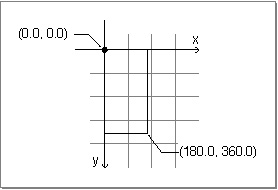
QuickDraw GX starts the drawing process by using the values in a shape's geometry. Geometry space is the space within which the fundamental position and dimensions of a shape object are defined. The numerical values in a shape's geometry define the shape's dimensions in geometry space.Suppose, for example, that the geometry of a rectangle consists of the points (0.0, 0.0) and (180.0, 360.0), as shown in Figure 1-6. In geometry space, the rectangle's origin is at (0.0, 0.0), its height is twice its width, and its area is 64,800.0 units square. No distance metric, such as points per inch, is defined for geometry space. Thus, the absolute size of a shape is undefined in geometry space.
Figure 1-6 A rectangle in geometry space
Geometry Space to Local Space
QuickDraw GX next modifies the shape's geometry by applying first the clip and then the mapping contained in the transform object attached to the shape. You typically use the transform's clip and mapping for application-specific purposes related to masking, moving, and distorting shapes within a document.Local space defines the location and dimensions of a shape after it has been modified by the transform mapping (as well as the style properties and the transform clip). Because mappings can translate, scale, rotate, skew, and otherwise distort geometries, the dimensions of a shape in local space can be quite different from what they are in geometry space.
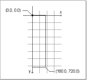
For example, if the rectangle shape discussed in the previous section had an associated transform whose mapping did nothing but scale the shape by 2.0 in the y-direction, its coordinates in local space would be (0.0, 0.0) and (180.0, 720.0), as shown in Figure 1-7. Its origin in local space would still be at (0.0, 0.0), but its height would be four times its width, and its area would be 129,600.0 units square. Like geometry space, local space has no distance metric. The absolute size of a shape is still undefined in local space.
Figure 1-7 A rectangle in local space (transform mapping applied)
The transform object includes a reference to a view port object, and local space orients a shape within its view port. Local space is the coordinate system interior to, or local to, that view port--hence the name local. Thus, the rectangle example in this section would have the same local coordinates--that is, the same position and shape within its view port--no matter how the view port itself might be scaled or distorted by its own mapping when it is converted to global space (described next).
Local Space to Global Space
QuickDraw GX next modifies the shape's dimensions by applying first the mapping and then the clip contained in the view port object attached to the shape's transform. You typically use the view port's mapping to position the contents of the window you are drawing into, and you use its clip to restrict drawing to the interior of the window.Global space defines the location and dimensions of a shape after the mapping (and clip) in its associated view port has been applied. Global space defines the real-world location and dimensions of a shape: coordinate values in global space represent distance in points (72 per inch) from the origin of the view group that the view port is part of. (Because it is the view group that relates view ports to view devices, objects in global space can have a specific spatial relationship with view devices, as described in the next section.)
For example, if the view port associated with the rectangle shape discussed in the previous sections had a mapping that did nothing but move the shape horizontally
by 200.0 and vertically by 200.0, the shape's coordinates in global space would be
(200.0, 200.0) and (380.0, 920.0), as shown in Figure 1-8. Its origin in global space would then be at (200.0 points, 200.0 points), its height would still be four times its width, and its area would be 129,600.0 points square (25 square inches).Figure 1-8 A rectangle in global space (view port mapping applied)
Thus, once a shape's dimensions have been converted from geometry space to local space to global space, they have a specific size and location and spatial relationship to other shapes in that view group. What remains for drawing, then, is for QuickDraw GX to convert this absolute (but device-independent) information to device-specific locations on output devices with specific pixel resolutions. That's where device space comes in.
Global Space to Device Space
Finally, QuickDraw GX modifies the shape's dimensions by applying first the mapping and then the clip of any view device object in the same view group as the view port. Device space defines the location and dimensions of a shape as displayed on a particular output device. The upper-left corner of the displayable area of a view device is at coordinate (0.0, 0.0) in device space. Unit distance between coordinates in device space represents one picture element, or pixel.The view device's mapping defines both its location in global space (as a translation factor) and its pixel size (as a scaling factor). For example, if your device is a 600 dots-per-inch printer, QuickDraw GX converts global space to device space when drawing by scaling each pixel by 8.33333, which is 600/72.
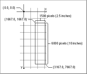
If the view device to which the rectangle shape discussed in the previous sections is drawn has a mapping that specifies no translation and a scale factor of 8.33333 both horizontally and vertically, that means that the view device's upper left corner is at
(0.0, 0.0) in global space and its pixel resolution is 600 per inch. In device space, then, the dimensions of the rectangle would be (1667.0, 1667.0) and (3167.0, 7667.0), as shown in Figure 1-9.Figure 1-9 A rectangle in device space (view device mapping applied)
It is seldom necessary to work in device space unless you are manipulating or hit-testing device bitmaps, because QuickDraw GX performs this kind of conversion for you. Most commonly, you define shapes in geometry space (using shape geometry), you position and modify them in local space (using the transform mapping), and you position and scale their view ports in global space (using the view port mapping).
- Identity mapping
- A mapping that contains values such that it has no effect at all when applied to a shape is called the identity mapping. If the identity mapping is used for all mappings involved in drawing, a shape's geometry directly defines its absolute size and position (in points), and the shape is rendered on a view device at a resolution of 72 pixels per inch.

Main | Page One | What's New | Apple Computer, Inc. | Find It | Contact Us | Help